Head Tracking: Examples

Head Tracking: Examples |
 |
In our implementation, the workstation's graphic acceleration and texture mapping capabilities were used to accelerate image warping and rendering; however, we didn't optimize the code in any other way. The resulting tracking speed is about one second per frame employing the difference decomposition technique and, on average, about seven seconds per frame using Powell. These performance figures include the time needed to extract the image from the compressed input movie and to save the stabilized texture map in a movie file.






|
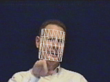
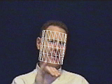
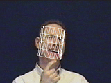
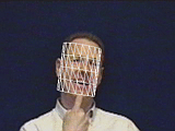
|
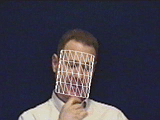
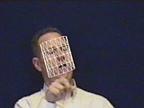
| Figure 1: Example input video frames and head tracking. The frames reported are 17, 23, 24, 39, 40, and 81 (left to right). Note the large amount of motion between two adjacent frames and the occlusions. |
Fig.1 shows a tracking of a person enthusiastically telling a story using American Sign Language. The sequence includes very rapid motion of the head and frequent occlusions of the face with the hand(s). Due to large interframe motion, we were unable to track reliably using the difference decomposition approach. However, despite the difficulty of the task, by using Powell's method stable tracking was achieved over the whole sequence of 93 frames. The resulting track is shown Fig.1.
 (A) |
 (B) |
 (C) |
 (D) |
 (E) |
 (F) |
 |
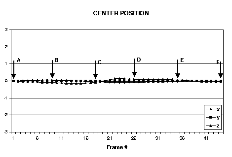 |
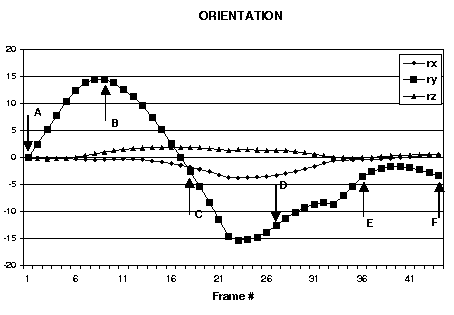
| Figure 2: Example input video frames taken from experiments in estimating head orientation and translation parameters: back-forth head gesture (nodding no). Every tenth frame from the sequence is shown. The estimated head orientation and translation are shown in the graphs. |
The next example demonstrates using the system for head gesture analysis. We considered two simple head gestures: up-down (nodding yes), back-forth (nodding no). Fig.2 shows every tenth frame taken from a typical video sequence of a back-forth gesture. Plots of estimated head translation and rotation are shown in the lower part of the figure. Note distinct peaks and valleys in the estimated parameter for rotation around the cylidrical axis; these correspond with the extrema of head motion.
 (A) |
 (B) |
 (C) |
 (D) |
 (E) |
 (F) |
 |
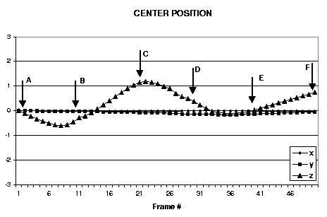 |
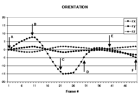
| Figure 3: Second head gesture example: up-down head gesture (nodding yes). Every tenth frame from the sequence is shown. The estimated head orientation and translation are shown in the graphs. |
Fig.3 depicts a typical video sequence of an up-down gesture. Again, there are distinct peaks/valleys in graphs of estimated translation and rotation parameters. Note that in this cases there appears to be a coupling between the rotation around the x-axis and translation along the z-direction (with opposite phase). This coupling is due to the different center of rotation for the head vs. the center of rotation for the cylindrical model. Even with this coupling, the estimated parameters are sufficiently distinctive to be useful in discrimination of the two nodding gestures.
Facial Expression Tracking in a Cylindrical Texture Map
Given the stabilized texture map provided using
the above described method,
we can track nonrigid deformation of the face. Our approach takes its
inspiration from Black and Yacoob: nonrigid facial motions are modeled
using local parametric models of image motion in the texture map. However,
our approach confines nonrigid motion to lie in a curved surface, rather
than in a flat plane.
Facial deformations are model with image templates, using the active blobs formulation. Each blob consists of a 2D triangular mesh with a color texture map applied, and deformation is parameterized in terms of each blob's low-order, nonrigid modes. During tracking, the rigid 3D model parameters are computed first, followed by estimation of the 2D blob deformation parameters using a robust error minimization procedure. For more details about the active blobs formulation, please see the active blobs technical report.
 (A) |
 (B) |
 (C) |
 (D) |
 (E) |
 (F) |
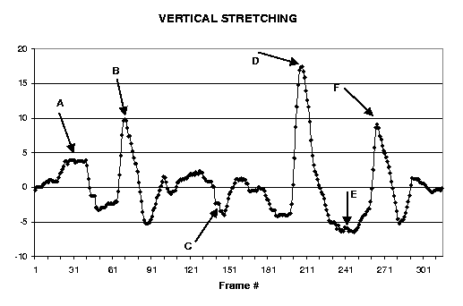 |
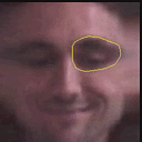
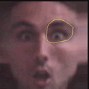
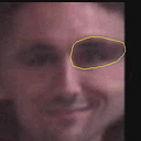
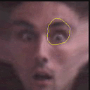
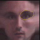
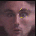
| Figure 4: Example of nonrigid tracking in the stabilized dynamic texture map to detect eyebrows raises. The graph shows resulting estimates of the blob's vertical stretching parameter. |
Figure 4 shows an example of using our approach. The head tracker generates a stabilized dynamic texture map and tracked the nonrigid motion of one eye to detect eyebrow raising. The figure shows a few relevant frames from the dynamic texture map with the nonrigid blob superimposed. Note that the eye and the eyebrow are included in the active blob model. This combined with the use of a robust error norm in the registration of the blob make the system almost insensitive to eye blinking.
The graph shows the estimated value of the blob parameter that describes vertical stretching of the blob. A vertical stretch of the blob corresponds to an eyebrow raising. The three peaks correspond to the three eyebrows raising occurred in the sequence. Note that the peaks correspond to values of the deformation parameter significantly larger than the mean rest value and is then easy to detect them. A similar technique can be applied to the nonrigid track of a closed mouth.
Last Modified: Oct 27, 1997